- дом
- Инверторы низкого напряжения
- Solution of overload fault
Fault Name:
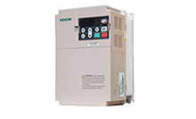
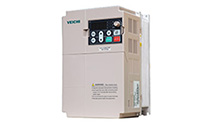
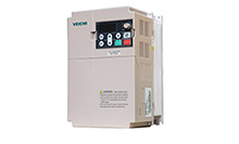
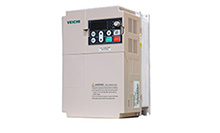
OC1 or OC3 is reported in the AC70E frequency inverter.
Fault Symptom:
The AC70E reports the OC1 or OC3 fault when starting and running, and if you remove output line, same problem happens and the field device cannot continue to run.
Causes:
The frequency inverter current detection chip is disturbed by the grounding cable, causing the frequency inverter to falsely report over-current fault.
Solutions:
Check whether the frequency inverter ground wire is contaminated; whether the control board to the power board UI, VI current feedback signal is consistent; use a clamp ammeter to detect whether the field load is too large; use a megohmmeter to detect whether the insulation between the motor windings is damaged; use a multimeter to detect whether the coil is shorted to ground or not;
Analysis:
This fault code is the actual condition of the motor load detected by the frequency inverter, which is used to protect the reliability of the motor running, ensure that the motor can run for a long time and prevent the site of the load is too large, the operator is operating in violation of the rules, causing the excessive motor load and burn out the motor due to sharply rising temperature. First remove the frequency inverter output and it will be still running, and measure the three-phase output with a multimeter, if the three-phase outputs are inconsistent, which indicates that there is an abnormal module drive voltage, resulting in unbalanced three-phase output, causing the current detection chip abnormal sampling, directly resulting in over-current fault; if the three-phase output voltages are nearly same, then connect them to the motor but run the inverter with no-load and use a clamp flow meter to measure whether the three phase output currents are consistent, simultaneously check the motor winding out and see if there are some problems, if it has, that means there are differences in the motor coils (may be short circuit between windings, or the number of motor coil turns, this phenomenon is rare) If not, you can find the problem from the frequency inverter itself. The current measured by the clamp current meter could be compared with the self-measurement current of it and you could accurately eliminate the possibility that the current measurement of itself is inaccurate and unreliable; if the above problems are not abnormal, the interference can be a possible reason, and the circuit may be caused due to on-site interference. Disturbance of the detection signal may cause abrupt changes in the feedback signal resulting in false alarms. Turn down the wave and observe if there is any change. If not, you can remove the grounding wire; continue to observe whether the fault is eliminated. If it is, you can check that the current detection and feedback signals are caused by the ground wire interference (This phenomenon can also be queried in the fault log) because the current detection signal is disturbed, it can cause the frequency inverter false alarm, over-current, overload, or phase losing, because the current detection chip ACS710TKLA-12CB, used in AC70E frequency inverter and it happens a lot, like over-current, output phase losing, ERR2, overload; All of these phenomena have occurred in Quzhou coating machine and Changshu machine tool, after on-site replacement and bring it back for analyzing, we found that the machine is normal; due to that the frequency inverters in the company rarely have grounding lines, such problems rarely happens, most of them occur on the site.
 Global - English
 Spanish - Español
 French - Français
 Russian - Pусский язык
 Chinese - 中文
 Korean - 한국어
 Vietnamese - Tiếng Việt

 Оставить сообщение